A Study on the Cooling Performance of Newly Developed Slice Die in the Hot Press Forming Process
by
 ,
,
Seung Hwan Lee
1 ,
,
Jaewoong Park
1,
Kiyoung Park
2,
Dong Keun Kweon
3,
Hyunwoo Lee
4,
Daeho Yang
4,
Hongrae Park
5 and
Jaeseung Kim
2,* 1
School of Aerospace and Mechanical Engineering, Korea Aerospace University, 76 Hanggongdaehang-ro, Deokyang-gu, Goyang-si 10540, Korea
2
Center for Robot Technology and Manufacturing, Institute of Advanced Engineering, 51 Goan-ro, Baegam-myeon, Cheoin-gu, Yongin-si 17180, Korea
3
Laon ENG Industrial Inc., Gueodeulmit-gil, Oedong-eup, Gyeongju-si 38205, Korea
4
MS AUTOTECH Co., Ltd., 16-9 Poseok-ro, Naenam-myeon, Gyeongju-si 38198, Korea
5
Daewoo Shipbuilding & Marine Engineering Co., Ltd., 125 Namdaemoon-ro, Jung-gu, Seoul 04521, Korea
*
Author to whom correspondence should be addressed.
Metals 2018, 8(11), 947; https://doi.org/10.3390/met8110947
Submission received: 21 September 2018
/
Revised: 30 October 2018
/
Accepted: 11 November 2018
/
Published: 14 November 2018
Abstract
:The cooling performance of a slice die is studied numerically and experimentally. The slice die is designed to improve the cooling performance compared to that of a conventional die that is generally used in the Hot Press Forming (HPF) process by modifying the cooling channel layout and arrangement. In order to understand the physical phenomenon of the slice die cooling performance, the cooling performance of the conventional die is also simulated and their results are compared with the slice die results. From the results of the maximum temperature of the blank and die and the temperature distribution of the blank, the slice die has considerably improved cooling performance. To validate the simulation results, the slice die is prototyped and a blank is produced by the HPF process. Blank temperatures are measured by a thermal imaging camera at several holding times. The simulation and experimental results of the blank temperatures are compared and agree with the error rate of 3%. In order to verify the quality of the produced blank, ultimate tensile stress, yield stress, and elongation tests are conducted for specimens that are extracted from the blank and are compared with existing literature results.
1. Introduction
Reinforcement of environmental regulations has become a global trend as environmental problems such as global warming and pollution have emerged as major issues. In the automotive industry, regulations of exhaust gas reduction and fuel efficiency improvement are changing from advisory implementation to compulsory implementation [1]. Due to this trend, the research topics of eco-friendly vehicles, vehicle weight reduction, and vehicle safety technology have come to the fore in the automotive industry [2]. The research of them is vital and has been actively studied [3].
The issues of vehicle weight reduction and vehicle safety technology are closely related to materials and car bodies [4]. In Europe, a car body was recently made of lightweight materials such as aluminum, magnesium, and carbon fiber reinforced plastic (CFRP), along with steel [5]. In Asia, Ultra High Strength Steel (UHSS) application has increased instead of steel sheets for a part of a car body.
Despite the development of materials, the processing technology of material molding fits to the existing material and this makes it difficult to process new materials. Especially, some car body parts using UHSS have increased strength, however they have very low elongation, resulting in a large number of defects in the press process. Hot Press Forming (HPF or Hot Stamping) is a new processing technology that was developed to solve this problem. HPF, a method developed by the Swedish company Plannja [6], was evaluated as an effective technology to satisfy the requirements of vehicle weight reduction and vehicle safety technology and was used in car manufacturing by various auto companies [7].
The HPF process is performed in the following sequence. (1) For a steel sheet that consists of Ferrite-Pearlite micro structures, temperature is increased up to austenitization temperature in the furnace; (2) The heated steel sheet is transferred to a die; (3) Through forming and quenching in the die, the steel sheet becomes a product with a martensite structure and a tensile strength of 1500 MPa [8]. During the HPF process, cooling is the key process determining the quality of a blank. Heat is transferred from a blank to a die and most of the heat that is transferred to the die is discharged through the cooling water that flows through cooling channels [9]. When a cooling rate is above 30 °C/s, austenitic microstructure is transformed into martensite and martensite improves the tensile strength of the blank.
The cooling process affects the quality of a die as well. If the cooling performance of the die is not sufficient, the heat that is transferred from the blank to the die cannot be discharged and remains in some part of the die [10]. As the HPF process is repeated, the remaining heat will maintain a certain temperature without temperature drop. If this situation keeps occurring, the relatively high remaining temperature in some part of the die will reduce the wear resistance of the die, thereby shortening the design life of the die.
Furthermore, the cooling performance influences the production efficiency. If the cooling time is shortened, the production cycle is decreased, which leads to productivity improvement. Hence, the cooling performance of the die is an important design variable that affects the blank quality, die quality, and production efficiency and must be considered in the HPF process design [11].
Several studies have been carried out to evaluate and improve the cooling performance of dies during the HPF process. Hoffmann et al. [12] optimized a cooling system of a die to keep the die temperature below 200 °C. From the optimized results, 8 mm diameter cooling channels were able to keep the average cooling rate of the die under 40 °C/s. George et al. [13] studied the effect of the cooling rate on microstructure generation in a blank. A 930 °C blank was inserted to dies at room temperature and at 400 °C, respectively, and martensite and bainite structure were formed in the blank in the room temperature die and 400 °C die, respectively. They found that 30 °C/s was a critical cooling rate for martensite formation during HPF operations. Liu et al. [14] investigated the optimization of a cooling system which satisfied the minimum 27 °C/s cooling rate required for the phase transformation of a blank during the HPF process. Using the optimization results, a die was manufactured and a blank was produced by the die. Then, the quality of the produced blank was verified by tensile tests. Lin et al. [15] numerically studied cooling systems that maximize die cooling performance and minimize thermal deformation by using a thermal-fluid-mechanical coupled method. The cooling performance of the die was maximized and the die deformation was minimized when the cooling channel diameter was 8 mm, the distance from the die surface to the cooling channel was within 8 mm, and the distance between cooling channels was 6–10 mm. LV et al. [16] explored a cooling system with linear shape cooling channels that satisfied the cooling rate of 27 °C/s and the strength of a die. Simulations were performed to find the best combination of design variables for cooling performance. When the diameter of the cooling channel was 8 mm, the cooling performance of the die was maximized and the strength of the die satisfied the requirement of the HPF process. Using the simulation results, the die was manufactured and a blank was produced by the HPF process. The quality of the blank was verified by the tensile and hardness tests. Chen et al. [17] used a segmented model to reduce the computational time while maintaining the accuracy of the calculation for HPF simulation. The segmented model was a part of the die that consisted of a straight side and a curved side. The optimized segmented model saved 92.6% of computational time compared to the non-segmented model.
Even though the cooling performance evaluation of the die was extensively researched and many important and meaningful results were derived, only few have prototyped a die due to high costs. Furthermore, the study of complicated blank shape having free foam is rare. According to the author’s knowledge, there are negligible studies that have evaluated simulations and experiments simultaneously. The aim of this research is to evaluate the cooling performance of a slice die numerically and experimentally. The slice die is newly developed technology and its cooling channel shape and position is modified to complement a conventional die that is used in the HPF process. When simulating the HPF process, the cooling water flow of the cooling channel is analyzed as well as the heat transfer including the thermal fluid of the entire die. In addition, an actual slice die is fabricated based on the simulation results and a blank is produced by the HPF process. The produced blank is verified by tensile tests. The material of the slice die is also verified by high temperature friction tests and hardness tests. In Section 2, the modeling and layout of the conventional and slice die are introduced. In Section 3, numerical simulation setup and experimental setup is described. In Section 4, the cooling performance of the slice die is numerically evaluated and the results are compared to the conventional die that is widely used for commercial production. For validation of the simulation results, a blank is produced by the slice die and the quality of the blank is experimentally examined. In Section 5, the results of Section 4 are discussed. Conclusions are followed in Section 6.
2. Die Models
The structure of the conventional and slice dies and their cooling channel layout are described in Section 2.1 and Section 2.2, respectively.
2.1. Conventional Die
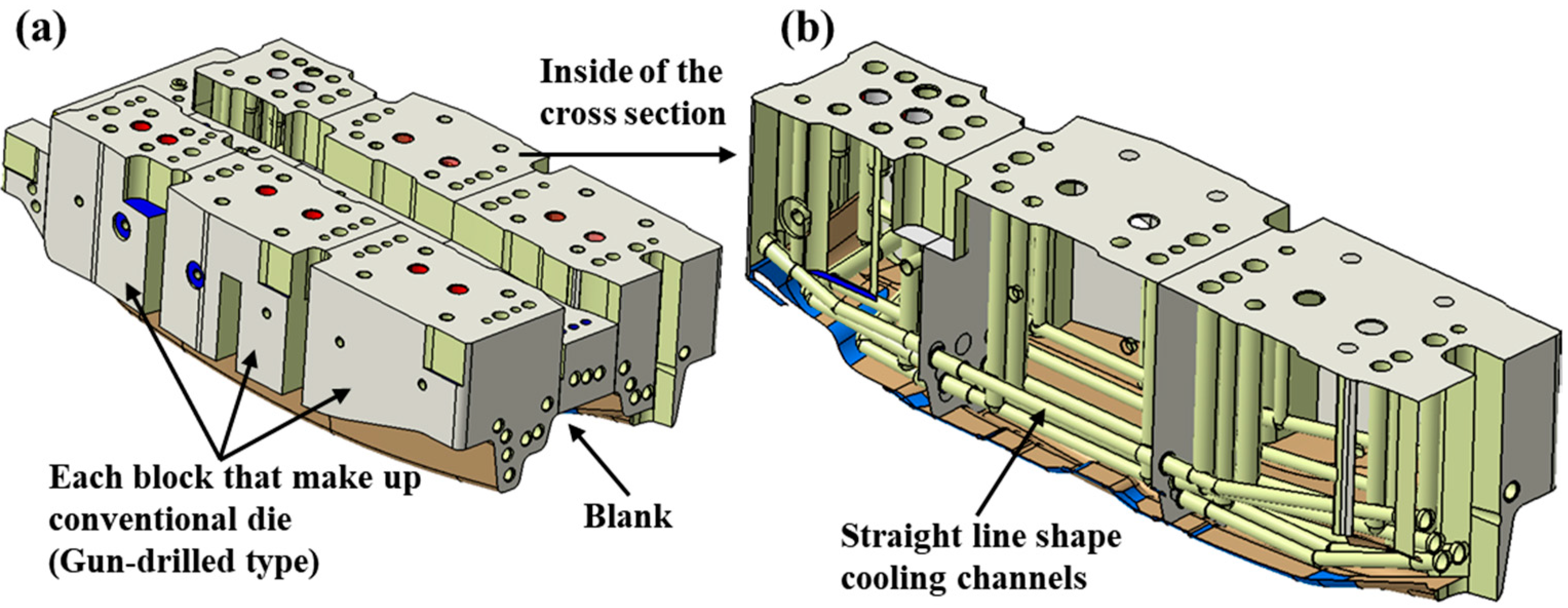
A conventional die that is generally used in the HPF process consists of an upper die (Gun-drilled type) and a lower die (Pocket type). Figure 1a shows the upper part of the conventional die and several blocks constitute one upper die. The cooling channel inside the upper die is machined with a straight drill and all cooling channels are linear shaped, as shown in Figure 1b. This linear shape makes it easy to process and repair the cooling channels. In addition, the interior of the gun-drilled type die has excellent structural strength because there is no empty space other than the cooling channels. The linear shape of the cooling channels, however, makes it hard to be machined along the surface of the curved die and the distances between the upper die surface and the cooling channels are not constant. For this reason, the heat transfer from a blank to the upper die during the HPF process can be uneven, resulting in a temperature variation in the blank. This temperature variation deteriorates the quality of the blank.
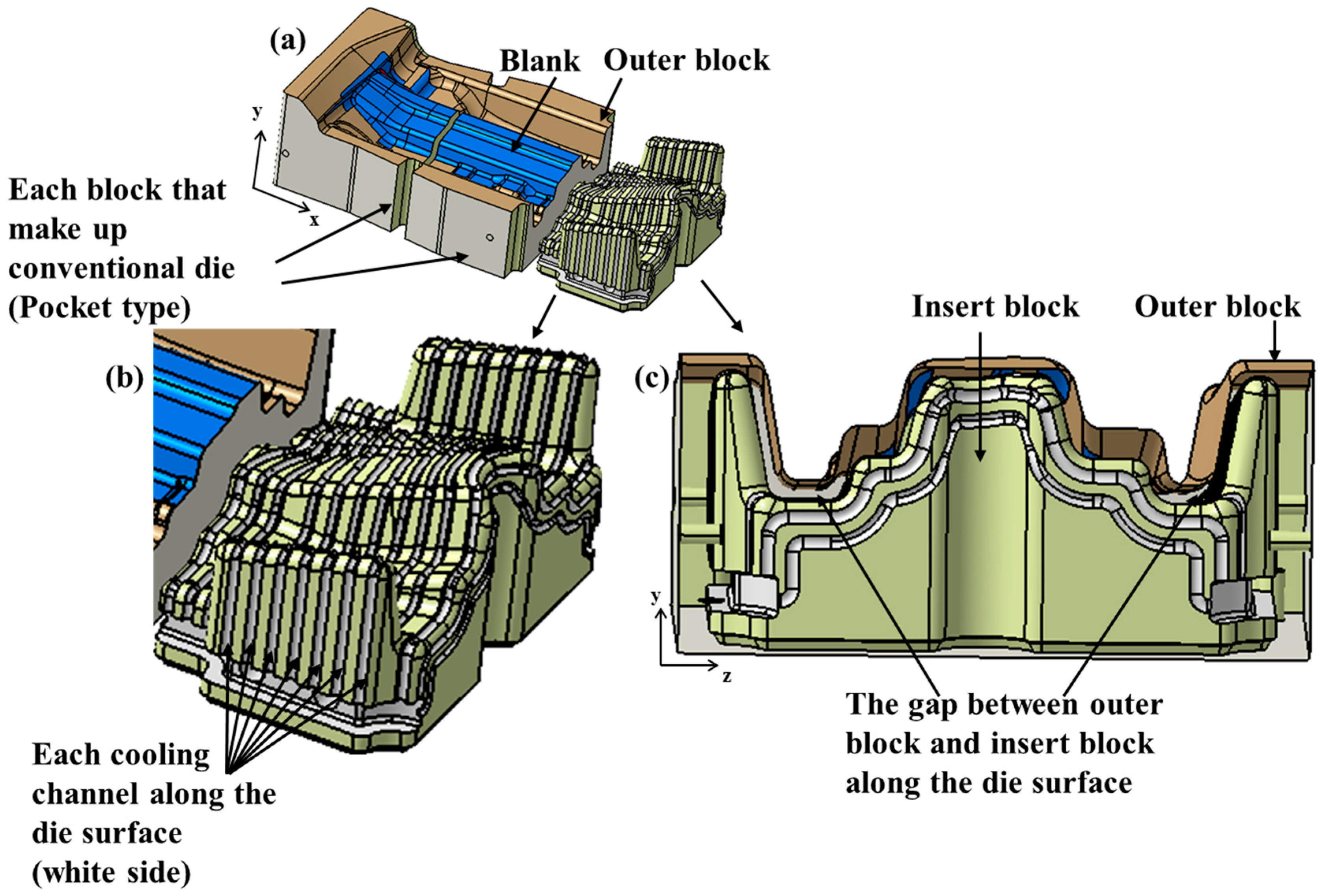
Figure 2a shows a lower die (pocket type) of the conventional die. After removing the inside of an outer block by a certain depth, an insert block in which the cooling channel is already machined is inserted into the lower die. As shown in Figure 2b, the cooling channel can be machined along the curved surface even if the die surface is curved and the distance between the die surface and the cooling channel is constant. Because of the constant distance, the heat transfer between the blank and the die is relatively uniform so that the pocket type die has good cooling efficiency. As shown in Figure 2c, a gap between the outer block and the insert block, however, makes the structure strength weak and causes water leakage due to cracks. Furthermore, machining costs are relatively high because the large portion of the outer block is removed during machining.
2.2. Slice Die
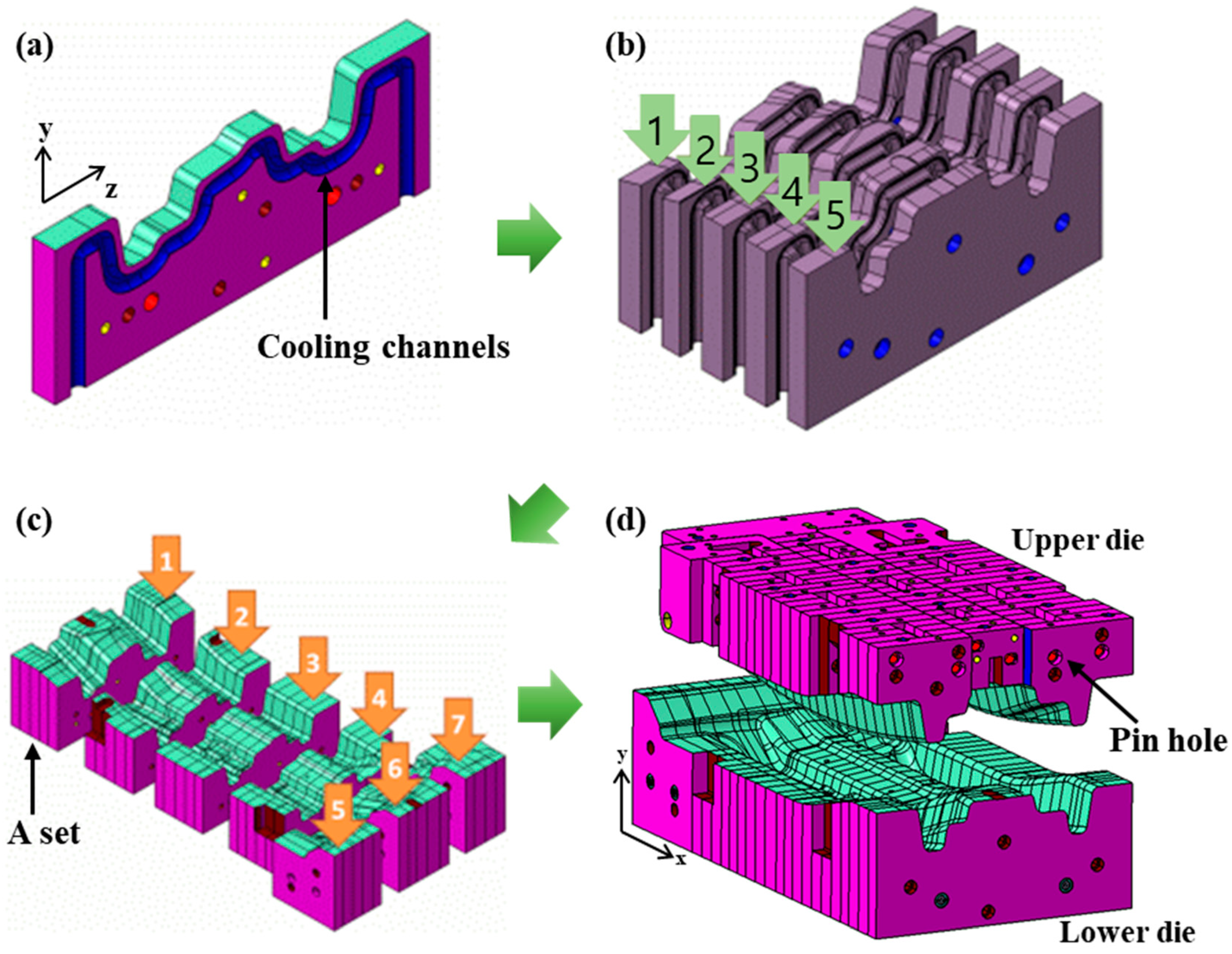
A slice die was proposed to overcome the disadvantages of the conventional dies, such as low cooling performance and weak structural strength. As shown in Figure 3a, the slice die consists of several divided pieces, while the conventional die consists of several blocks to make a single die. After machining half of the cooling channels on both sides (yz side) of each die piece, several die pieces are assembled and constitute a set, as shown in Figure 3b. Then, several sets are combined (Figure 3c) and comprise a die (Figure 3d). Particularly, the slice die is designed as a free-form surface with a blank shape along both the upper and lower die surface and the cooling channel is machined along the die surface to a shallow and uniform depth in the -y direction, as shown in Figure 3c.
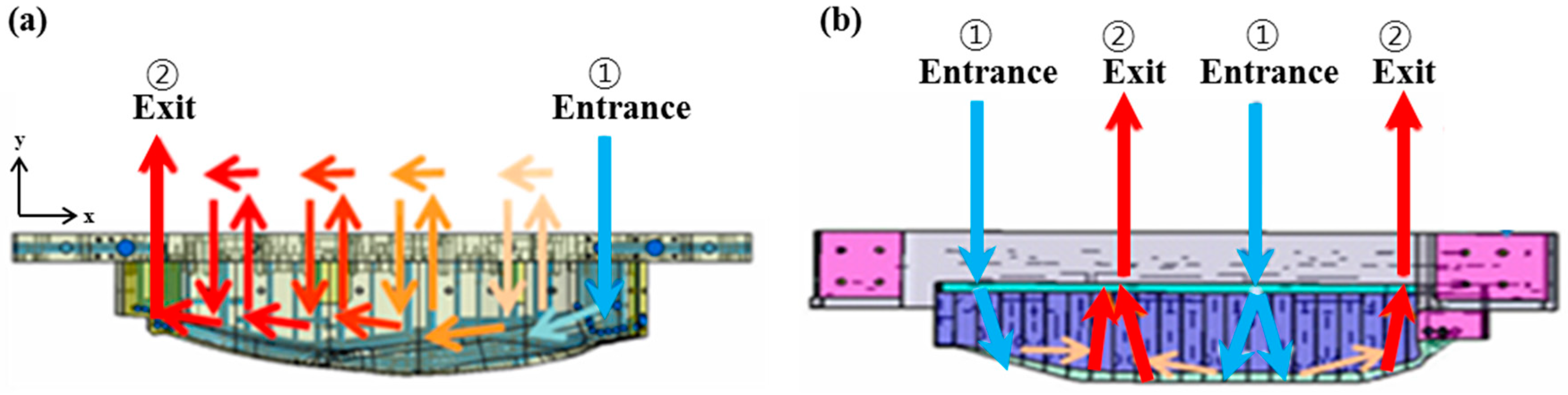
Furthermore, the slice die can control the cooling water flow. Figure 4a,b shows the cooling water flow on the upper part of the conventional die and the slice die, respectively. As shown in Figure 4a, the conventional die has only one entrance and exit and the cooling water flowing into the entrance flows along the arrows repeatedly up and down, left and right, and then flows to the exit. This cooling water flow method maximizes and evenly distributes the heat transfer between the blank and the die, however the cooling channels of the gundrill type die become long and complicated. On the contrary, as shown in Figure 4b, the slice die has two entrances and exits. The cooling water flows into two entrances at the same time and flows to the two exits through a short travel route compared to the conventional die. This method decreases the circulation period of the cooling water and increases the cooling efficiency. Furthermore, the lower die of the slice die has improved structural strength and durability compared to the pocket die as the structure shape of the lower die does not need a gap. Moreover, raw material loss and repair cost are reduced leading to cost saving compared to pocket dies.
3. Setup
Simulation set-up for heat and fluid analysis of the conventional and slice dies are described in Section 3.1. The experimental set-up is described in Section 3.2 including a manufactured die, a blank, and test devices.
3.1. Simulation Setup
The analytical models that were used for this study were the conventional die that is generally used in the HPF process and the newly developed slice die. The governing equations describing the physical phenomena of heat and fluid for numerical simulation are continuity equation, conservation of momentum equation, and energy balance equation. The energy balance equation was used to predict the heat transfer and temperature distribution.
In order to predict the airflow and temperature distribution in the control volume, a k-ε turbulence model [18] was used with the assumption that the stress generated by the turbulence is proportional to the velocity gradient. In this model, the turbulent viscosity coefficient is expressed by turbulent kinetic energy and the turbulent kinetic energy dissipation rate.
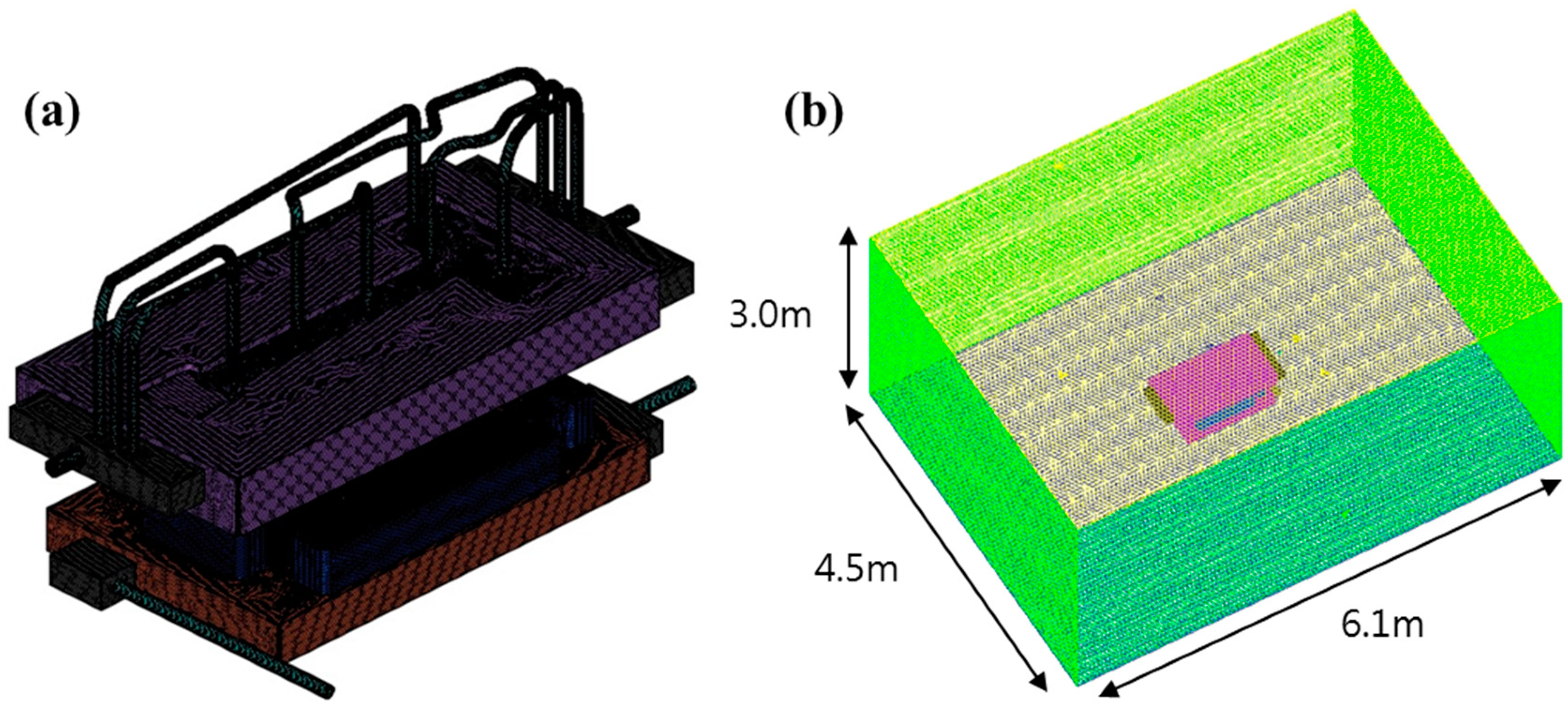
The numerical analysis sequence of the model was as follows. First, various parts of the conventional and slice die models were obtained by Computer Aided Design (CAD) software (Dassault Systèmes, France). After examining the interference between the shapes, the models were aligned and combined (CAD clean up), and mesh was created by Fluent, a commercial software that is used for Computational Fluid Dynamics (CFD). Figure 5 shows the meshed model of the solid part (left) and the exterior volume (right). Specifically, 7.3 million polyhedral cells formed on the solid part and the exterior volume was based on tetrahedral. Then, working fluid and boundary conditions were set. The temperature of the outside the die was 27 °C with the incompressible ideal gas condition. The cooling water with 10 °C was continuously supplied. The used thermal conductivity of the die was 30.5 W/mK. As a boundary condition, a volume heat source was set as the blank initial temperature and the inlet cooling water flow rate was 90 L/min.
3.2. Experimental Setup
For validation of the simulation results, a slice die was fabricated at the actual production conditions. The cooling channel of the slice die was processed within 8 mm in the −y direction from the die surface, while the cooling channel of the conventional die was unevenly distributed and had to be machined by more than 12 mm in the −y direction from the die surface. As shown in Figure 3, a water tightness test was performed after the assembly process. Using a calibrated pressure gauge, a leakage of cooling fluid (water) was checked by flowing cooling fluid (water) into the cooling channels in the upper and lower dies at a pressure of 5 bar for 2 h. After confirming no leakages, two dies were installed in a 5000-ton class press. During a blank production using the die, a product production cycle was considered and the product production cycle was decided by blank quality and productivity. The production cycle was directly proportional to the holding time in the HPF process. The holding time was 12 s when the blank was manufactured using the conventional die. Blanks were produced with varying holding times so that each blank was produced at a holding time of 5, 7, 9, and 11 s. The blank temperatures were measured when the upper die was opened immediately after the blank production using a thermal imaging camera (FLIR Co., Oregon, OR, USA) with emissivity of 0.9 and a reflection temperature of 40 °C. When measuring the maximum blank temperature, the temperature of the blank surface was measured at the holding time of 5, 7, 9, and 11 s.
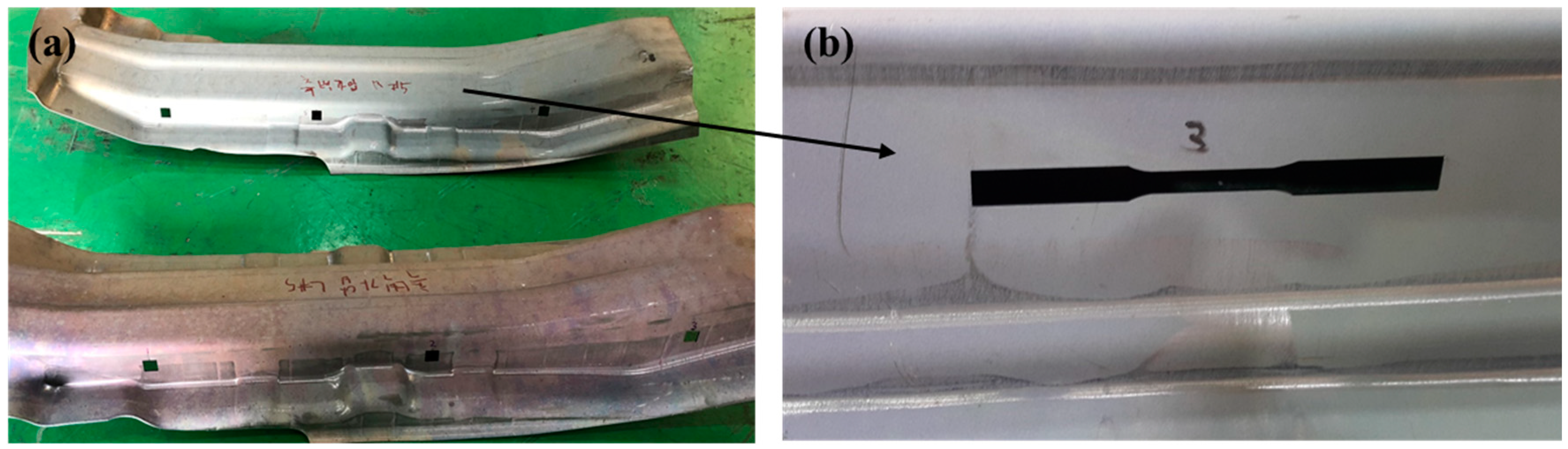
From the blank that was manufactured by the slice die using the HPF process (Figure 6a), 15 tensile test specimens were produced (Figure 6b) and five tensile tests were performed to measure the tensile strength, yield strength, and elongation. The tensile tests were conducted according to the American Society for Testing and Materials (ASTM) E8/E8M-16a standard.
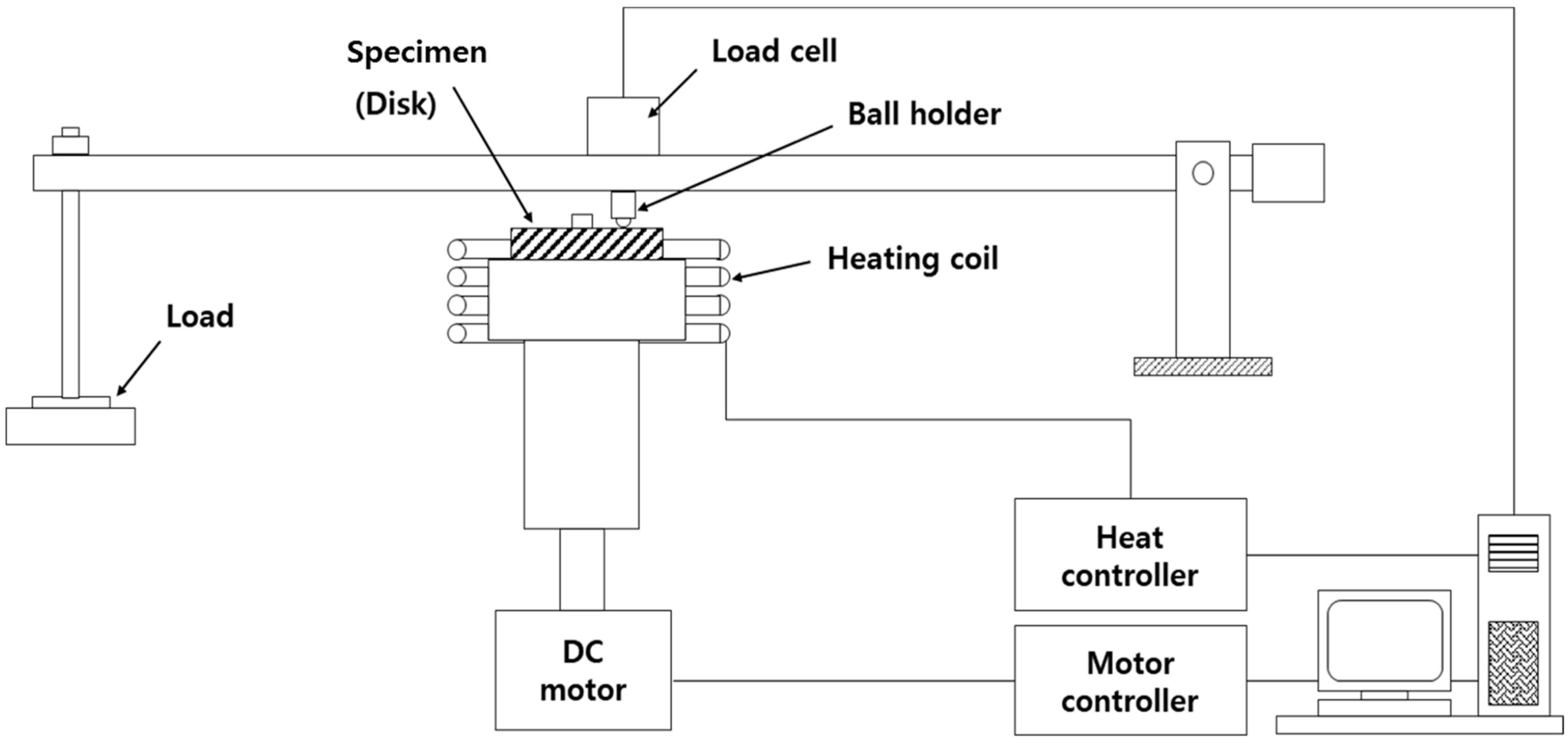
In addition, the wear resistance and durability of the die was confirmed by wear tests. Figure 7 is a schematic view of a high temperature wear tester. This device is a ball-on-disk type and a load of 5 N was applied to a 9.2 mm diameter ball made of SKD11 material. Then, a SKD61 material with a circular disk shape was placed under the loaded ball and was rotated to obtain friction coefficient data. The motor rotated the disk and the controller controlled the rpm of the motor. For high temperature wear tests, an induction heater heated the disk and the temperature of the disk was higher than that of the die during the HPF process.
The test conditions are shown in Table 1. The wear test pieces with a thickness of 5 mm and a diameter of 50 mm were tested by heating to 250 °C. The sliding velocity of the disc was set to 0.24 m/s and the friction tests were carried out while moving the track diameter from 25 mm to 1500 m.
4. Results
In Section 4.1, the cooling performance of the conventional and slice die are studied numerically. In Section 4.2, the simulation results of the blank temperature are compared with the experiment results. To verify the produced blank quality, tensile specimens are tested in terms of ultimate tensile stress, yield stress, and elongation.
4.1. Cooling Performance of the Dies
Holding time is one of the key process parameters that determine product quality and productivity in the production of vehicle parts through the HPF process. The holding time is the total time spent for deformation and cooling. Precisely, holding time is defined from the moment when the upper die comes into contact with the lower die to the moment when the upper die comes off the lower die after the blank forming and the cooling process.
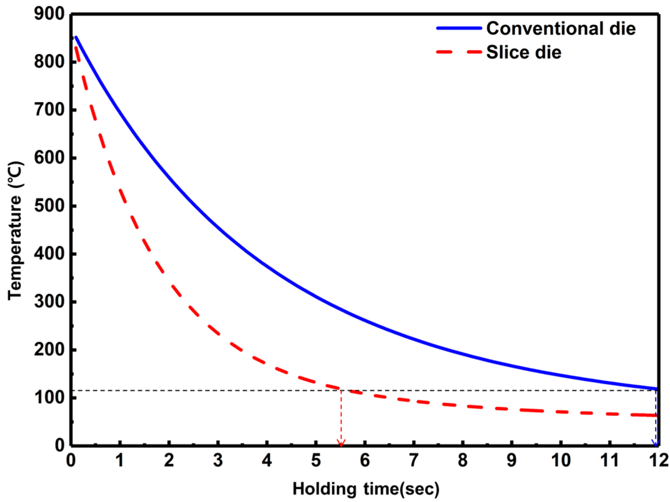
Figure 8 shows the maximum temperature of the blank regarding holding time in HPF simulation for conventional and slice dies. The initial blank temperature at the simulation is set as 870 °C which is the actual blank temperature at the HPF process when the blank is transferred to the die after being heated in a furnace. To be consistent with the actual HPF process, the simulation is also carried out for a holding time of 12 s.
From the simulation results, the blank of the conventional and slice dies are cooled to about 120 °C and 63 °C, respectively at 12 s holding time. The sliced die reaches 120 °C in about 5.5 s which is 6.5 s less time than that of the conventional die. That is, in the case of the conventional die, a blank can be removed from the die by opening the upper and lower dies at a holding time of 12 s, while for the slice die, a blank can be removed after a holding time of about 5.5 s. Especially, from one to five seconds holding time, a dramatic temperature drop occurs and the average cooling rate of the slice die is about 144 °C/s, while the conventional die is about 65.5 °C/s. For the whole holding time duration, the blank cooling rate of the slice die and the conventional die are about 67 °C/s and 57 °C/s, respectively.
Figure 9 shows the HPF simulation results of the temperature distribution of the blank when the upper and lower dies are opened at a holding time of 12 s. For the conventional die, the maximum temperature of the blank is about 150 °C and its region is where there are no cooling channels in the upper and lower dies (Figure 9a). The minimum temperature region of the blank is at the edge and the difference between the maximum and minimum temperatures is about 60 °C. On the other hand, for the slice die, the maximum blank temperature is about 70 °C and the high temperature region is evenly distributed throughout the blank (Figure 9b). The minimum temperature region of the blank is at the edge, which is the same as in the previous case, and the maximum temperature and the minimum temperature difference is about 28 °C.
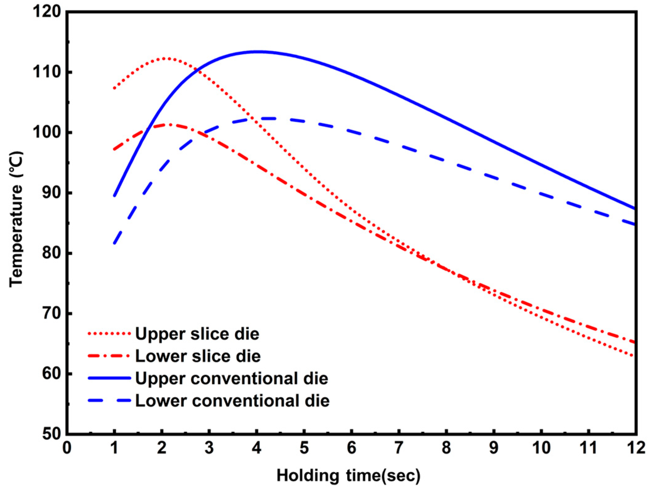
Figure 10 shows the maximum temperature change of the die according to the holding time when the upper and lower dies are closed after the upper die lowering. During the holding time, the exerted pressure ranges between about 4 and 8 MPa. For the two die types, the temperature of the upper die is higher than that of the lower die throughout the whole holding time. The role of the upper die is to press the blank by moving up and down, while the lower die is fixed and has less load so that the lower die has more cooling channels than the upper die. The temperature of the two die types rises at the beginning of the holding time at which heat is transferred from the blank and then decreases as the cooling progresses. The temperature graphs of the upper and lower dies at each type have a similar trend as a whole. The temperature graph of the slice die tends to shift to the left compared to the conventional die. In addition, the time required for the conventional die to reach the maximum temperature is about four seconds, while the time for the slice die to reach the maximum temperature is about two seconds. In addition, by examining the cooling rate of the die from the maximum temperature to the end of the HPF process, the upper and lower part of the conventional die is 3.25 °C/s and 2.25 °C/s, respectively and the upper and lower part of the slice die is 5.2 °C/s and 3.7 °C/s, respectively. Hence, the cooling rate of the slice die is higher than that of the conventional die.
4.2. Experimental Results
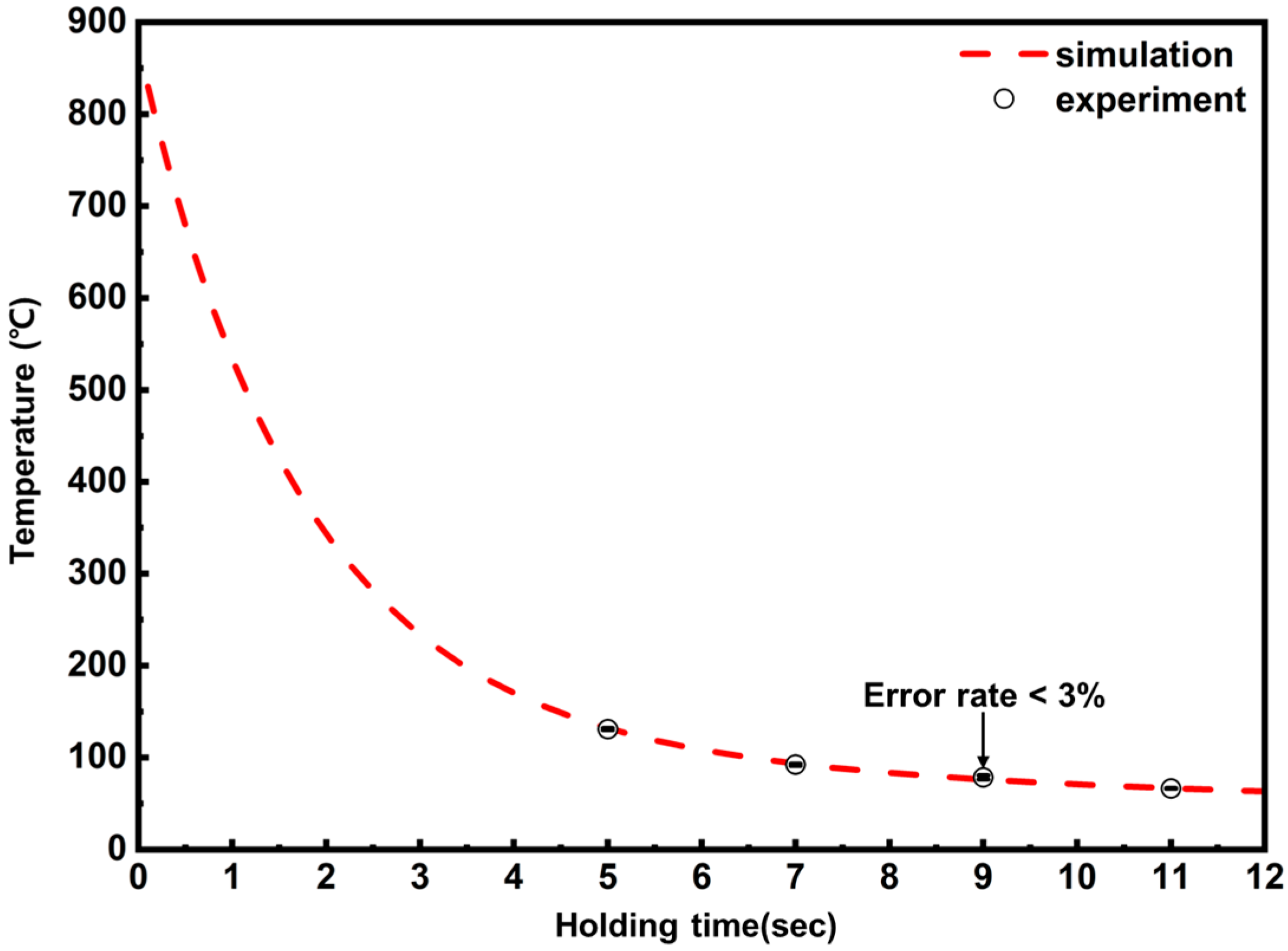
To validate the slice die cooling performance shown in Section 4.1, an actual slice die was prototyped and blank temperature was measured at a holding time of 5, 7, 9, and 11 s. Figure 11 shows the comparison of blank temperature from the simulation (red line) and the experimental (black circle). Very good agreement is observed between the simulation and experiment results. At the holding time of 5, 7, 9, and 11 s, the error rate of the simulation and experiments are 0.9%, 1.3%, 2.9%, and 0.6%, respectively and the overall error rate is within 3%. As far as the blank temperature in the conventional die is concerned, the temperature was about 130 °C at a holding time of 12 s.
In order to compare the quality of the blanks produced from the conventional and slice dies, 15 tensile test specimens were machined from the blanks, respectively. Ultimate Tensile strength (UTS), yield stress, and elongation of this specimen were measured five times. In the case of the specimen from the slice die, the UTS of the blank was about 1475 MPa, the yield strength was about 1125 MPa, and the elongation was about 10%. In the case of the specimen from the conventional die, the UTS of the blank was about 1426 MPa, the yield strength was about 1078 MPa, and the elongation was 8.7%. These values agree with the results of Bardelcik et al. [19]. Hence, the blank quality that was produced by the slice die meets the performance requirement of the HPF process.
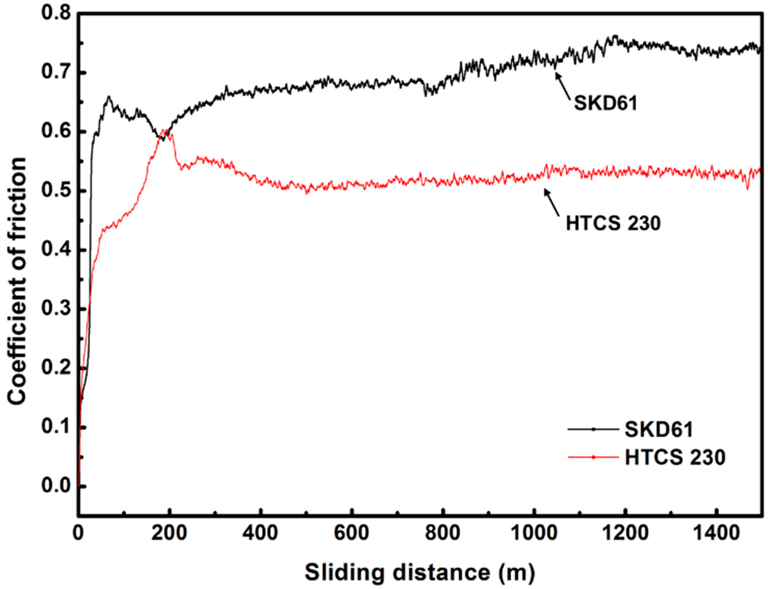
Figure 12 shows the friction test results of SKD61 and HTCS230 materials that were used in conventional dies and slice dies, respectively at 250 °C. The friction tests were conducted at a relative humidity of air of 50 ± 5%. The temperature of 250 °C is the risen temperature due to the accumulation of heat in the part of the conventional die when it produces about 100,000 parts. The friction behavior of both materials varies greatly from 0 to 200 m due to wear debris. The conventional die material (SKD61) has a larger average friction coefficient than that of the slice die material (HTCS 230). For the slice die material (HTCS 230), the coefficient of friction converged after 500 m without fluctuation, whereas the friction coefficient of the conventional die material (SKD61) continuously increased with relatively high fluctuation in the 200–1200 m range of sliding distance. Hence, SKD61 has better friction resistance at 250 °C than HTCS230.
For the material’s effect on the die, a hardness test was additionally carried out at room temperature and 250 °C. Additional specimens were prepared, the center was cut, the section was polished, and the hardness was measured at the center of the section. The hardness values were measured five times at room temperature and 250 °C using Micro Vickers (HV 1) and the average of them are shown in Table 2. From the hardness test results, the hardness values of the sliced die materials are higher than those of the conventional die materials at room temperature and 250 °C. This result shows that the die manufactured using HTCS230 has better durability compared to the die manufactured using SKD61.
5. Discussion
As shown in Section 4, the cooling rate of the blank in the slice die is faster than that of the conventional die and the slice die has superior cooling performance compared to the conventional die. These results can be explained as follows.
First, the position of the cooling channel in the slice die is closer to the die surface than in the conventional die. The linear shape of the cooling channels in the conventional upper die is changed into a curved shape along the die surface (blank surface) in the slice die. In addition, the lower part of the conventional die had to have a certain thickness to avoid the weakness of the structural strength during the cooling channel machining. As the lower die is replaced with the slice die type, the inside of the lower die is filled up except for the cooling channel so that a structural strength can be secured at the reduced thickness. Hence, the transferred heat can be quickly discharged to the outside when the heat transfers from the blank to the die.
Second, the shape of the cooling channels in the slice die is curved. As the cooling channel is machined at each die piece, the shape of the cooling channel can be changed to a curved shape and the number and surface area of cooling channels can be increased by about 19% and 32%, respectively compared with the conventional die.
Third, the slice die has a short circulation period of the cooling water. As the arrangement of the cooling channels is changed, cooling water flows into several pairs of entrances and cooling efficiency is increased while cooling water flows into only one entrance in the conventional die.
As shown in Figure 10, the cooling rate of the upper die is higher than that of the lower die in both die types even though lower dies have more cooling channels than those of the upper dies. It is inferred that the total amount of heat that is transferred from the blank to the lower die is larger than that of the upper die and this causes relatively higher cooling rate in the upper dies.
6. Conclusions
The newly developed slice die is proposed to enhance the quality and productivity of blank and is designed to improve the cooling performance compared to that of the conventional die that is used in the HPF process. In the present study, the cooling performance of the slice die and conventional die was numerically evaluated by studying the maximum temperature of the blank and die and the temperature distribution of the blank. To validate the simulation results, a blank was produced by the actual HPF process and the quality of the blank was verified by the tensile tests. In addition, abrasion and hardness of the slice die material was tested. From the results that were discussed in this paper, the following conclusions are made:
The slice die is designed to a finely divided structure and the cooling channel shape is changed from a straight line to a curve along the blank shape. As a result of the structure and arrangement of the cooling channels, the slice die reduced holding time by about 30% compared to the conventional die and can improve the product quality by making homogenous martensite inside the blank.
- During one to five seconds holding time, the average cooling rate of the slice die and the conventional die is about 144 °C/s and 65.5 °C/s, respectively. For the whole holding time duration, the blank cooling rate of the slice die and the conventional are about 67 °C/s and 57 °C/s, respectively. Overall, the slice die has better cooling performance than that of the conventional die.
- At a holding time of 12 s, the maximum temperature of the blank in the conventional die is about 150 °C and its region is where cooling channels do not exist in the upper and lower dies. For the slice die, the maximum blank temperature is about 70 °C and the maximum temperature region is evenly distributed throughout the blank. In addition, the temperature distribution of the blank in the slice die is more uniform than that of the conventional die so that blank warping can be expected to be reduced. Therefore, the slice die can improve the durability and design life of the die.
- To validate the simulation results, the slice die model was prototyped and the blank was produced by the HPF process. During the blank production, blank temperatures were measured at a holding time of 5, 7, 9, and 11 s and agreed with the simulation result within a 3% error rate. Then, the material property of the blank was tested to check the blank quality. From the blank tensile test, the average tensile strength was 1475 MPa, the yield strength was 1125 MPa, and elongation was 10%. Compared with the previous study, the quality of the blank satisfies the requirement of the HPF process.
- Friction and hardness tests were performed to understand the material’s effects on the die. From the friction tests at 250 °C, the slice die material, HTCS230, has about 28% less friction coefficient and less fluctuation than that of SKD61. In addition, the hardness test at 250 °C shows that the hardness value of HTCS230 is higher than SKD61, so there is less damage to the surface of HTCS230 during the HPF process.
Author Contributions
J.K., S.H.L. and K.P. conceived and designed this study. K.P., D.K.K., H.L., and D.Y. performed the simulation and experiment. J.P., H.P., and S.H.L. drafted this paper.
Funding
This paper was supported by the Korea Evaluation Institute of Industrial Technology (KEIT) grant that was funded by the Ministry of Trade, Industry and Energy (MOTIE) (No.10063421).
Conflicts of Interest
The authors declare no conflict of interest.
References
- So, H.; Faßmann, D.; Hoffmann, H.; Golle, R.; Schaper, M. An investigation of the blanking process of the quenchable boron alloyed steel 22MnB5 before and after hot stamping process. J. Mater. Process. Technol. 2012, 212, 437–449. [Google Scholar] [CrossRef]
- Merklein, M.; Wieland, M.; Lechner, M.; Bruschi, S.; Ghiotti, A. Hot stamping of boron steel sheets with tailored properties: A review. J. Mater. Process. Technol. 2016, 228, 11–24. [Google Scholar] [CrossRef]
- Åkerström, P. Modeling and Simulation of Hot Stamping. Ph.D. Theses, Luleå University of Technology, Luleå, Sweden, 2006. [Google Scholar]
- Neugebauer, R.; Altan, T.; Geiger, M.; Kleiner, M.; Sterzing, A. Sheet metal forming at elevated temperatures. CIRP Ann. 2006, 55, 793–816. [Google Scholar] [CrossRef]
- Kum, J.; Park, O.; Hong, S. Tough High Thermal-Conductivity Tool Steel for Hot Press Forming. J. Korean Soc. Manuf. Process. Eng. 2016, 15, 130–134. [Google Scholar] [CrossRef]
- Karbasian, H.; Tekkaya, A.E. A review on hot stamping. J. Mater. Process. Technol. 2010, 210, 2103–2118. [Google Scholar] [CrossRef]
- Mori, K.; Bariani, P.F.; Behrens, B.A.; Brosius, A.; Bruschi, S.; Maeno, T.; Merklein, M.; Yanagimoto, J. Hot stamping of ultra-high strength steel parts. CIRP Ann. 2017, 66, 755–777. [Google Scholar] [CrossRef]
- Naderi, M.; Ketabchi, M.; Abbasi, M.; Bleck, W. Analysis of microstructure and mechanical properties of different high strength carbon steels after hot stamping. J. Mater. Process. Technol. 2011, 211, 1117–1125. [Google Scholar] [CrossRef]
- Xing, Z.W.; Bao, J.; Yang, Y.Y. Numerical simulation of hot stamping of quenchable boron steel. Mater. Sci. Eng. A 2009, 499, 28–31. [Google Scholar] [CrossRef]
- Abdollahpoor, A.; Chen, X.; Pereira, M.P.; Xiao, N.; Rolfe, B.F. Sensitivity of the final properties of tailored hot stamping components to the process and material parameters. J. Mater. Process. Technol. 2016, 228, 125–136. [Google Scholar] [CrossRef]
- Li, X.; Chang, Y.; Wang, C.; Hu, P.; Dong, H. Comparison of the hot-stamped boron-alloyed steel and the warm-stamped medium-Mn steel on microstructure and mechanical properties. Mater. Sci. Eng. A 2017, 679, 240–248. [Google Scholar] [CrossRef]
- Hoffmann, H.; So, H.; Steinbeiss, H. Design of Hot Stamping Tools with Cooling System. CIRP Ann. 2007, 56, 269–272. [Google Scholar] [CrossRef]
- George, R.; Bardelcik, A.; Worswick, M.J. Hot forming of boron steels using heated and cooled tooling for tailored properties. J. Mater. Process. Technol. 2012, 212, 2386–2399. [Google Scholar] [CrossRef]
- Liu, H.; Lei, C.; Xing, Z. Cooling system of hot stamping of quenchable steel BR1500HS: Optimization and manufacturing methods. Int. J. Adv. Manuf. Technol. 2013, 69, 211–223. [Google Scholar] [CrossRef]
- Lin, T.; Song, H.-W.; Zhang, S.-H.; Cheng, M.; Liu, W.-J. Cooling Systems Design in Hot Stamping Tools by a Thermal-Fluid-Mechanical Coupled Approach. Adv. Mech. Eng. 2015, 6. [Google Scholar] [CrossRef]
- Lv, M.; Gu, Z.; Li, X.; Xu, H. Optimal Design for Cooling System of Hot Stamping Dies. ISIJ Int. 2016, 56, 2250–2258. [Google Scholar] [CrossRef] [Green Version]
- Chen, J.; Gong, P.; Liu, Y.; Zheng, X.; Ren, F. Optimization of hot stamping cooling system using segmented model. Int. J. Adv. Manuf. Technol. 2017, 93, 1357–1365. [Google Scholar] [CrossRef]
- Hu, P.; He, B.; Ying, L. Numerical investigation on cooling performance of hot stamping tool with various channel designs. Appl. Therm. Eng. 2016, 96, 338–351. [Google Scholar] [CrossRef]
- Bardelcik, A.; Salisbury, C.P.; Winkler, S.; Wells, M.A.; Worswick, M.J. Effect of cooling rate on the high strain rate properties of boron steel. Int. J. Impact Eng. 2010, 37, 694–702. [Google Scholar] [CrossRef]
Figure 1.
Conventional upper die (Gun-drilled type): (a) Shape; (b) Cooling channels inside the die.
Figure 1.
Conventional upper die (Gun-drilled type): (a) Shape; (b) Cooling channels inside the die.

Figure 2.
Conventional lower die (Pocket type): (a) Shape; (b) Cooling channel structure; (c) Insert and outer block.
Figure 2.
Conventional lower die (Pocket type): (a) Shape; (b) Cooling channel structure; (c) Insert and outer block.

Figure 3.
Slice die: (a) Each piece of the slice die; (b) Pieces for one set; (c) Sets for the lower slice die; (d) Upper and lower slice die.
Figure 3.
Slice die: (a) Each piece of the slice die; (b) Pieces for one set; (c) Sets for the lower slice die; (d) Upper and lower slice die.

Figure 4.
Cooling water flow in (a) conventional upper die and (b) slice upper die.

Figure 5.
Meshed model of the numerical analysis (a) Solid part mesh; (b) Exterior volume mesh.

Figure 6.
(a) Blank manufactured by the HPF (Hot Press Forming) process; (b) Tensile test specimen from the blank.
Figure 6.
(a) Blank manufactured by the HPF (Hot Press Forming) process; (b) Tensile test specimen from the blank.

Figure 7.
Schematic of the wear test devices.

Figure 8.
Maximum blank temperature of the conventional and slice dies according to holding time for the HPF process simulation.
Figure 8.
Maximum blank temperature of the conventional and slice dies according to holding time for the HPF process simulation.

Figure 9.
Temperature distribution at holding time 12 s (a) Conventional die; (b) Slice die.

Figure 10.
Temperature change at the contacted area with the blank in the conventional and slice dies according to holding time.
Figure 10.
Temperature change at the contacted area with the blank in the conventional and slice dies according to holding time.

Figure 11.
Temperature change of the blank made by the slice die.

Figure 12.
Friction coefficients of die materials at 250 °C.


Table 1.
Wear test conditions.
| Wear Test Conditions of the Test Machine | |
|---|---|
| Tribometer type | ball-on-disk type |
| Temperature | 250 °C |
| Relative humidity | 25% |
| Applied normal load | 5.0 N |
| Sliding velocity | 0.24 m/s |
| Wear track diameter | 25 mm |
| Sliding distance | 1500 m |
Table 2.
Micro-vickers hardness value (HV 1).
| Temperature | SKD61 | HTCS230 |
|---|---|---|
| 25 °C | 225.5 | 381.1 |
| 250 °C | 220.0 | 386.8 |
© 2018 by the authors. Licensee MDPI, Basel, Switzerland. This article is an open access article distributed under the terms and conditions of the Creative Commons Attribution (CC BY) license (http://creativecommons.org/licenses/by/4.0/).
Share and Cite
MDPI and ACS Style
Lee, S.H.; Park, J.; Park, K.; Kweon, D.K.; Lee, H.; Yang, D.; Park, H.; Kim, J. A Study on the Cooling Performance of Newly Developed Slice Die in the Hot Press Forming Process. Metals 2018, 8, 947. https://doi.org/10.3390/met8110947
AMA Style
Lee SH, Park J, Park K, Kweon DK, Lee H, Yang D, Park H, Kim J. A Study on the Cooling Performance of Newly Developed Slice Die in the Hot Press Forming Process. Metals. 2018; 8(11):947. https://doi.org/10.3390/met8110947
Chicago/Turabian StyleLee, Seung Hwan, Jaewoong Park, Kiyoung Park, Dong Keun Kweon, Hyunwoo Lee, Daeho Yang, Hongrae Park, and Jaeseung Kim. 2018. "A Study on the Cooling Performance of Newly Developed Slice Die in the Hot Press Forming Process" Metals 8, no. 11: 947. https://doi.org/10.3390/met8110947
Note that from the first issue of 2016, this journal uses article numbers instead of page numbers. See further details here.